How to use FB_SolenoidBank
Overview
This function block will allow you to use a network and any number of cylinders to write to the memory as needed. In this sample, we will use a Festo CPX-FB38 64Byte. This module from Festo can have many kinds of IO modules, but in this sample, it is only solenoids.
Function Block
The FB_Festo function block extends from the FB_SolenoidBankBase function block. Then it adds 64 bytes of input data and 64 bytes of output data.
| FUNCTION_BLOCK FB_Festo EXTENDS FB_SolenoidBankBase
VAR
//Initial array of cylinders
Inputs AT %I* : ARRAY[0..63] OF USINT;
Outputs AT %Q* : ARRAY[0..63] OF USINT;
END_VAR
|
Methods
MapIO()
The MapIO method will set the extended output and if there is a retracted output, it will set that one too. It assumes that the retracted output is the IO point after the extended.
| SetOutput(Configuration[x].SolenoidOutputNumber,Configuration[x].ipSolenoid.ExtendOutput);
IF Configuration[x].SolenoidType = E_SolenoidType.Double OR Configuration[x].SolenoidType = E_SolenoidType.DoubleFeedback THEN
SetOutput(Configuration[x].SolenoidOutputNumber+1,Configuration[x].ipSolenoid.RetractOutput);
END_IF
|
SetOutput()
This method will take the number and map it into the correct byte and bit of that byte. It is called from the MapIO method multiple times.
1
2
3
4
5
6
7
8
9
10
11
12 | METHOD SetOutput
VAR_INPUT
Output : UINT;
Value : BOOL;
END_VAR
VAR
myByte : WORD;
myBit : WORD;
myBitMask : USINT;
pOutput : POINTER TO USINT;
END_VAR
|
1
2
3
4
5
6
7
8
9
10
11
12
13
14
15
16 | // Find the Byte and the Bit of that Byte
myByte := Output / 8;
myBit := Output MOD 8;
//Create the mask for to use for turning on/off
myBitMask := TO_USINT(EXPT(2, myBit));
//Set the pointer to the byte
pOutput := ADR(Outputs[myByte]);
// Turn on or off as needed the bit of the byte
IF Value THEN
pOutput^ := pOutput^ OR myBitMask;
ELSE
pOutput^ := pOutput^ AND (NOT myBitMask);
END_IF
|
MAIN POU
The main program has all the cylinder variables and the FestoBank.
 1
 2
 3
 4
 5
 6
 7
 8
 9
10
11
12
13
14
15
16
17
18
19
20 | PROGRAM MAIN
VAR
SimpleCylinder : FB_SingleSolenoid := (Name := 'Simple Cylinder');
SimpleCylinder2 : FB_SingleSolenoid := (Name := 'Simple Cylinder2');
SimpleCylinder3 : FB_SingleSolenoid := (Name := 'Simple Cylinder3');
SimpleCylinder4 : FB_SingleSolenoid := (Name := 'Simple Cylinder4');
SimpleCylinder5 : FB_SingleSolenoid := (Name := 'Simple Cylinder5');
SimpleCylinder6 : FB_SingleSolenoid := (Name := 'Simple Cylinder6');
SimpleCylinder7 : FB_SingleSolenoid := (Name := 'Simple Cylinder7');
SimpleCylinder8 : FB_SingleSolenoid := (Name := 'Simple Cylinder8');
DoubleSolenoid : FB_DoubleSolenoid := (Name := 'Dobule Solendoid Cylinder');
SingleFeedback : FB_SingleSolenoidFeedback := (Name := 'Single with Feedback');
DoubleFeedback : FB_DoubleSolenoidFeedback := (Name := 'Double with Feedback');
//Bank
FestoBank : FB_Festo;
//Init
Init : BOOL;
END_VAR
|
Initialize
Here is the cylinder HMI control being allowed and adding the solenoids to the bank. In the AddSolenoid method, it takes the interface to a cylinder function block, the bit number of the Output and the type of solenoid. The bit number in this example must be between 0-511 since it is 64 bytes of data. If the solenoid type is of Double then the retract output is assumed to be right after the extend output. The AllowHMIControl just give the visualization the ability to extend and retract the cylinders.
 1
 2
 3
 4
 5
 6
 7
 8
 9
10
11
12
13
14
15
16
17
18
19
20
21
22
23
24
25 | IF NOT Init THEN
FestoBank.AddSolenoid(ipCylinder := SimpleCylinder, Number := 0, SolenoidType := E_SolenoidType.Single);
FestoBank.AddSolenoid(ipCylinder := SimpleCylinder2, Number := 1, SolenoidType := E_SolenoidType.Single);
FestoBank.AddSolenoid(ipCylinder := SimpleCylinder3, Number := 2, SolenoidType := E_SolenoidType.Single);
FestoBank.AddSolenoid(ipCylinder := SimpleCylinder4, Number := 3, SolenoidType := E_SolenoidType.Single);
FestoBank.AddSolenoid(ipCylinder := SimpleCylinder5, Number := 4, SolenoidType := E_SolenoidType.Single);
FestoBank.AddSolenoid(ipCylinder := SimpleCylinder6, Number := 5, SolenoidType := E_SolenoidType.Single);
FestoBank.AddSolenoid(ipCylinder := SimpleCylinder7, Number := 6, SolenoidType := E_SolenoidType.Single);
FestoBank.AddSolenoid(ipCylinder := SimpleCylinder8, Number := 7, SolenoidType := E_SolenoidType.Single);
FestoBank.AddSolenoid(ipCylinder := DoubleSolenoid, Number := 8, SolenoidType := E_SolenoidType.Double);
FestoBank.AddSolenoid(ipCylinder := SingleFeedback, Number := 16, SolenoidType := E_SolenoidType.SingleFeedback);
FestoBank.AddSolenoid(ipCylinder := DoubleFeedback, Number := 24, SolenoidType := E_SolenoidType.DoubleFeedback);
SimpleCylinder.AllowHMIControl();
SimpleCylinder2.AllowHMIControl();
SimpleCylinder3.AllowHMIControl();
SimpleCylinder4.AllowHMIControl();
SimpleCylinder5.AllowHMIControl();
SimpleCylinder6.AllowHMIControl();
SimpleCylinder7.AllowHMIControl();
SimpleCylinder8.AllowHMIControl();
DoubleSolenoid.AllowHMIControl();
SingleFeedback.AllowHMIControl();
DoubleFeedback.AllowHMIControl();
Init := TRUE;
END_IF
|
 1
 2
 3
 4
 5
 6
 7
 8
 9
10
11
12 | SimpleCylinder.CyclicLogic();
SimpleCylinder2.CyclicLogic();
SimpleCylinder3.CyclicLogic();
SimpleCylinder4.CyclicLogic();
SimpleCylinder5.CyclicLogic();
SimpleCylinder6.CyclicLogic();
SimpleCylinder7.CyclicLogic();
SimpleCylinder8.CyclicLogic();
DoubleSolenoid.CyclicLogic();
SingleFeedback.CyclicLogic();
DoubleFeedback.CyclicLogic();
FestoBank.CyclicLogic();
|
EtherCAT Setup
In this setup, there is one box that is a CPX-FB38 module.
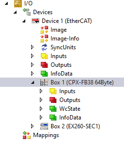
It has the following Process Data. 64 bytes Input and 64 bytes Output
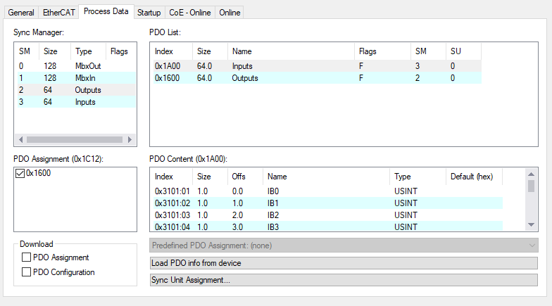
Input Mapping (IB0-IB63)

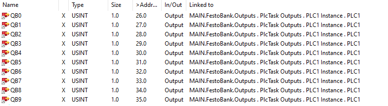
Output Mapping (QB0-QB63)
Notes
This example was only tested in simulation and the memory checked to see it function. Once it is tested with real hardware, there may be some slight modifications needed.